Begin 2015 I’ve started on my first IoT project; building a smart heat recovery system (or warmte terugwin unit – WTW). Back then I wrote an article (in Dutch, see here) explaining why I felt this was necessary and my initial approach. I never could have expected the journey I started, I had opened Pandora’s box.
I must admit it has been a fun ride with many ups and some downs (otherwise there would have been no ups)! I’ve learned so many things, ranging from hardware design, PCB’s, software coding and the IoT ecosystem in general. Mainly it’s been a journey refreshing my memory, some things I haven’t done since I was 17 and I was eager on learning it again.
In this article I want to share with you the result of *almost* 3 years of learning; my IoT project is finished
Result
Whenever the humidity is too high in the bathroom – someone’s taking a shower / bath – the heat recovery system automatically boosts to the highest state (3). When the humidity is low enough it goes back to the desired state. Additionally, a push notification is send to my phone when the filter requires changing.
I ended up adding a mechanical fan to suck more air out of the bathroom, switched with a smart power plug.
Components
- RenoventHR module ***
- Automation Engine
- Smart Humidity Sensor
- Smart power plug
COTS components
Let’s start with the easy part. I’ve used common of the shelf (COTS) hardware to read the humidity in the bathroom and switch the added mechanical fan (bonus). Since I had some equipment from Xiaomi laying around I ended up using:
- Xiaomi Mi Smart Temperature and Humidity Sensor
- Xiaomi Mi Zigbee Smart Socket Plug
- Xiaomi Mi Smart Home Gateway 2
Having connected modules doesn’t make a solution smart, only when the components are connected with each other (with some logic) it can truly become smart. For that I needed “home automation” software, I went with Home Assistant as that’s widely distributed and supports many hardware out of the box. Later in this article I’ll share the logic to make this a smart solution and the configuration associated.
RenoventHR module
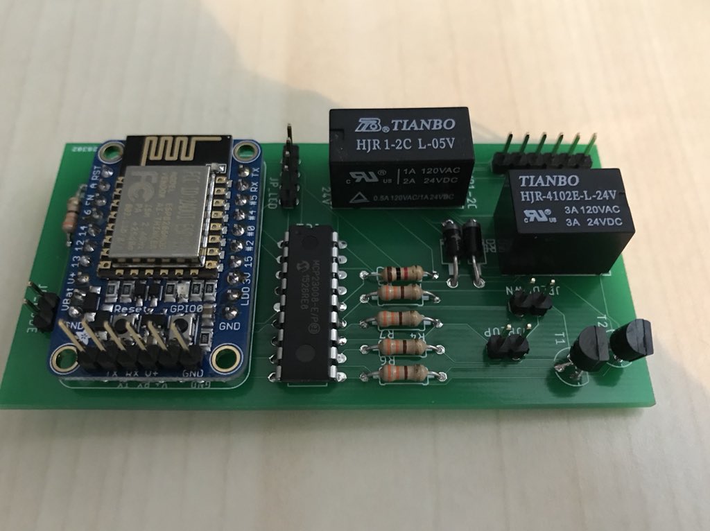
This is the actual module I’ve built. My baby.
It is named RenoventHR since as connect this module to a Brink RenoventHR
When designing this module, I had the following design requirements:
- Mode/state information should be visible on the device;
- Mode/state should be configurable manually (physical, with buttons);
- Mode/state should be configurable via a mobile device;
- Mode/state should be configurable via automation system (REST + MQTT);
- Filter change indicator should be readable via automation system (REST + MQTT);
- Connected via Wi-Fi;
- Configuration should be configurable (no passwords in the code);
- Hardware should appear OEM (no loose wires);
- Needless to say, the WAF (wife acceptance factor) is important.
I’ve tried to make the solution replicable, for you (the reader) but also for the people in my neighborhood with similar systems. The module consists of two parts; hardware and software. Let’s start with the hardware as that’s the part I’m most proud of, also because that’s where the learning curve was highest.
Hardware
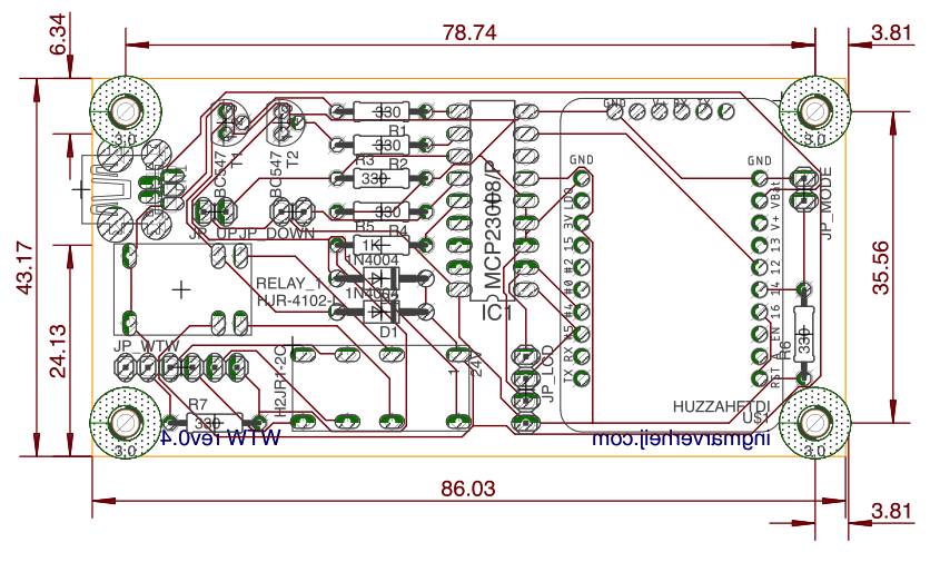
The module is a custom-built PCB which I designed in AutoDesk EAGLE. After many (…) prototypes on breadboards I finally ordered some PCBs. Though the first attempt was unsuccessful, revision 0.4 is now in production. Not bad.
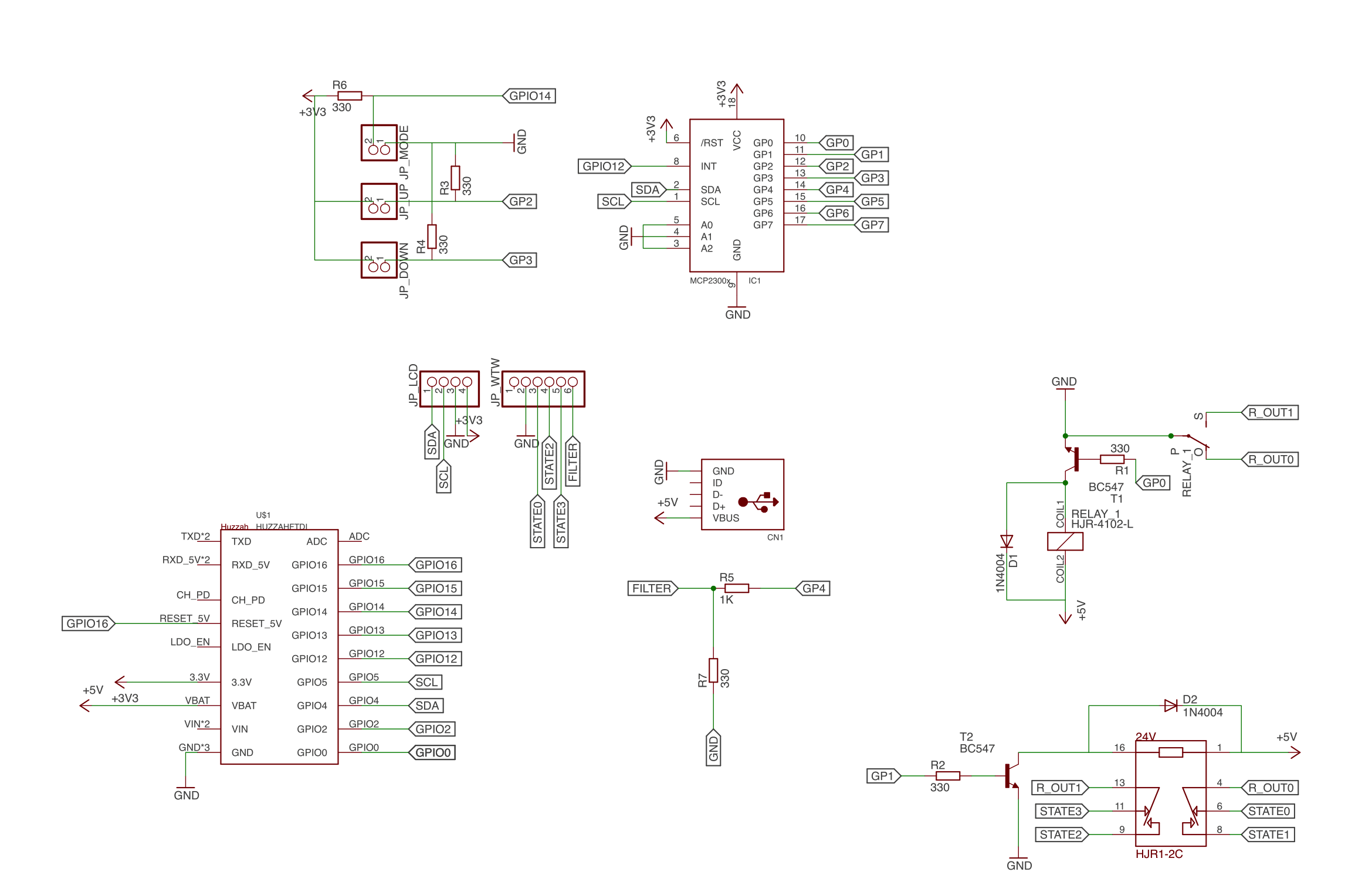
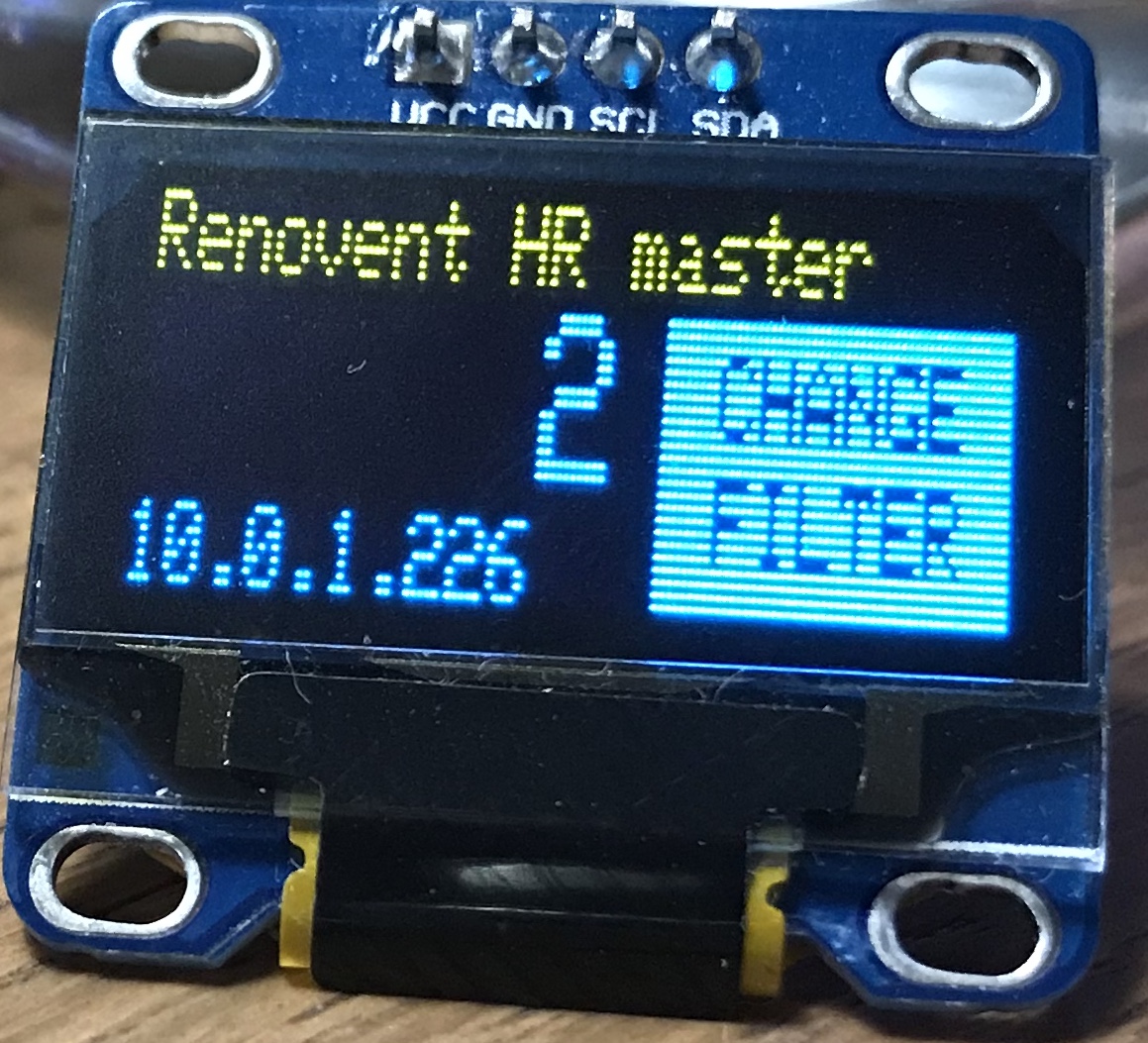
The design is based around an ESP8266, a low-cost but very powerful and flexible module which features Wi-Fi and GPIO pins. The onboard EEPROM is used to store the configuration and current mode/state (so it persists on a reboot). To simplify the design the module is using the Adafruit HUZZAH ESP8266 which costs roughly $10. Because of my requirements I found the amount of available GPIO pins on the ESP8266 was not enough, so I added a 8 bit I/O port expander (MCP23008). This port expanded also comes with configurable interrupt pins which was just what I needed. To mimic the physical switch and the 4 modes (0,1,2 and 4) it features two relays (one SPST and one SPDT). Manually switching up and down is down with two push buttons and changing the operation mode (from normal to setup-mode) is done with a rocker switch. A small 0.96” OLED screen is attached to show the state/mode and the IP address of the module. Mini USB provides a steady 5V to the module.
I’ve uploaded the files: schematic, board and part list on GitHub. Feel free to use them, feel encouraged to share if you used (or modified) them. The link is below.
Software
Another thing I like about the ESP8266 is that I can run “Arduino code” on it. Not only is the IDE and syntax easy, there’s a huge community that provides a wealth of information. I won’t run you through the entire code here (it’s on GitHub) but I’ll share the functionality with you.
I’ve added some comments in the code to explain the functionality and used the Hungarian notation for variables (well, my interpretation of it 😆 ).
Operating mode
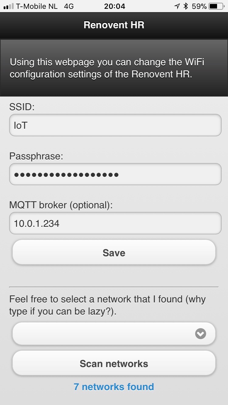 The device has two operating modes: normal and setup. In the setup mode the device acts as a Wi-Fi Access Point (SSID RenoventHR) and serves a webpage. The IP address is shown on the OLED so the user knows where to point the browser to.
On the webpage the following can be configured:
- SSID: The SSID of the Wi-Fi network the device should connect to in normal
- Passphrase: The passphrase for the Wi-Fi network
- MQTT broker (optional): The address of the MQTT broker the device should connect to in normal If no address is provided the device won’t try to connect.
Since I’m lazy I included a button to scan for available networks.
The data is stored in the EEPROM of the ESP8266. This way no user data is stored in the code and I can reconfigure it without the need to re-program.
The normal mode connects to the Wi-Fi network read from the EEPROM (during boot). It hosts a webserver to change the mode via a mobile device (AJAX webpage), via HTTP REST and MQTT. An interrupt is attached to the rocker switch so the device will automatically reboot and start in the other mode when the switch is switched. Getting an ESP8266 to reliable reboot wasn’t all that easy, but connecting GPIO16 to the reset pin and issuing ESP.deepsleep() does the trick.
Interfaces
Interfacing with the module can be done with 4 methods (these interfaces are only available in the normal operating mode):
- Physically
- Webpage
- HTTP REST
- MQTT
Physical
 There are two pushbuttons connected to the device to which interrupts are attached. After a button is pressed the wtwState is raised/lowered. Immediately the relays are switched to the desired state and – when configured – the new setting is broadcasted via MQTT.
The OLED display will display the current wtwState.
Webpage
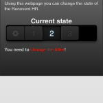
An AJAX webpage is available on the IP address of the module (which is visible on the OLED screen), the page is optimized for a mobile phone. Using this webpage, a user can manually change the wtwState. The page is dynamic, meaning that if the state is changed with another method this is reflected on the webpage.
If the filter needs to be changed this is visible on the webpage.
HTTP REST
Status information about the module can be obtained by issuing the following HTTP REST command:
https://<address>/status
This will return a JSON file containing the following information:
- wtwState: the current wtwState [0/1/2/3]
- changeFilter: 0 = filter is good, 1 = filter needs to be changed
The wtwState can we set using a HTTP REST command:
https://<address>/changeState?state=value
where value is the new state. This will return the same JSON file as with /status
MQTT
When the connection with the MQTT broker – for whatever reason – is disconnected it will retry every 5 seconds (configurable). The module publishes the following topics:
- RenoventHR/wtwState: the current wtwState [0/1/2/3]
- RenoventHR/changeFilter: 0 = filter is good, 1 = filter needs to be changed
The information is broadcasted every 5 seconds (configurable) but also when the state is changed using another method.
It also subscribes to the following topic:
- RenoventHR/setWTWstate: Sets the new wtwState [0/1/2/3]
Security
During the design of the module I’ve thought hard about the security implications.
Though the possible impact on a breach is limited – so a hacker can change the mode/state of my WTW, meh – there’s a bigger risk. Since the device is connected via Wi-Fi there’s a risk that:
- Someone can sniff the credentials;
- The credentials are read from the EEPROM of the module.
To mitigate the first risk as much as possible I’m uploading the latest available firmware of the ESP8266. For instance, the latest ESP8266 firmware is protected against KRACK (link). The second problem I took for granted. I could have encrypted the credentials before I stored them in the EEPROM, but since the software (and thus encryption keys) are on GitHub that’s kind off useless.
Another possible risk is that a malicious user could sniff unprotected traffic. I haven’t implemented HTTPS or SMQTT (using TLS), simply because this is a home automation module… not an enterprise module.
TIP: When you’re planning on running this module (or any other IoT device) my advice is to create a separate Wii SSID and network segment to reduce the risks. After all, when the Wi-Fi credentials are stolen from your unsafe IoT device… your network if exposed.
Home Assistant
 To make the solution smart, in fact just to make it a solution, I needed a platform that allowed me to connect different components and add some intelligence. I went with Home Assistant as that’s widely distributed and supports many hardware out of the box. What’s also convenient is that it comes with a MQTT broker out of the box.
The configuration is stored in the YAML file format. This all starts with the configuration.yaml file, I’ve used some !include statements to split the configuration in separate files. Secrets are all stored in a separate file (secrets.yaml). The relevant parts of the files are provided below.
configuration.yaml
Being the base configuration file, it contains the most “random” information. The relevant parts are:
- enabling the MQTT broker;
- including files for automation, group, notify and sensors (described below);
- Configuring the Xiaomi Agara gateway details
- Define an alert which sends a notification every 12h if the filters needs to be changed;
- Define a boolean (switch) to indicate the WTW is in boost mode;
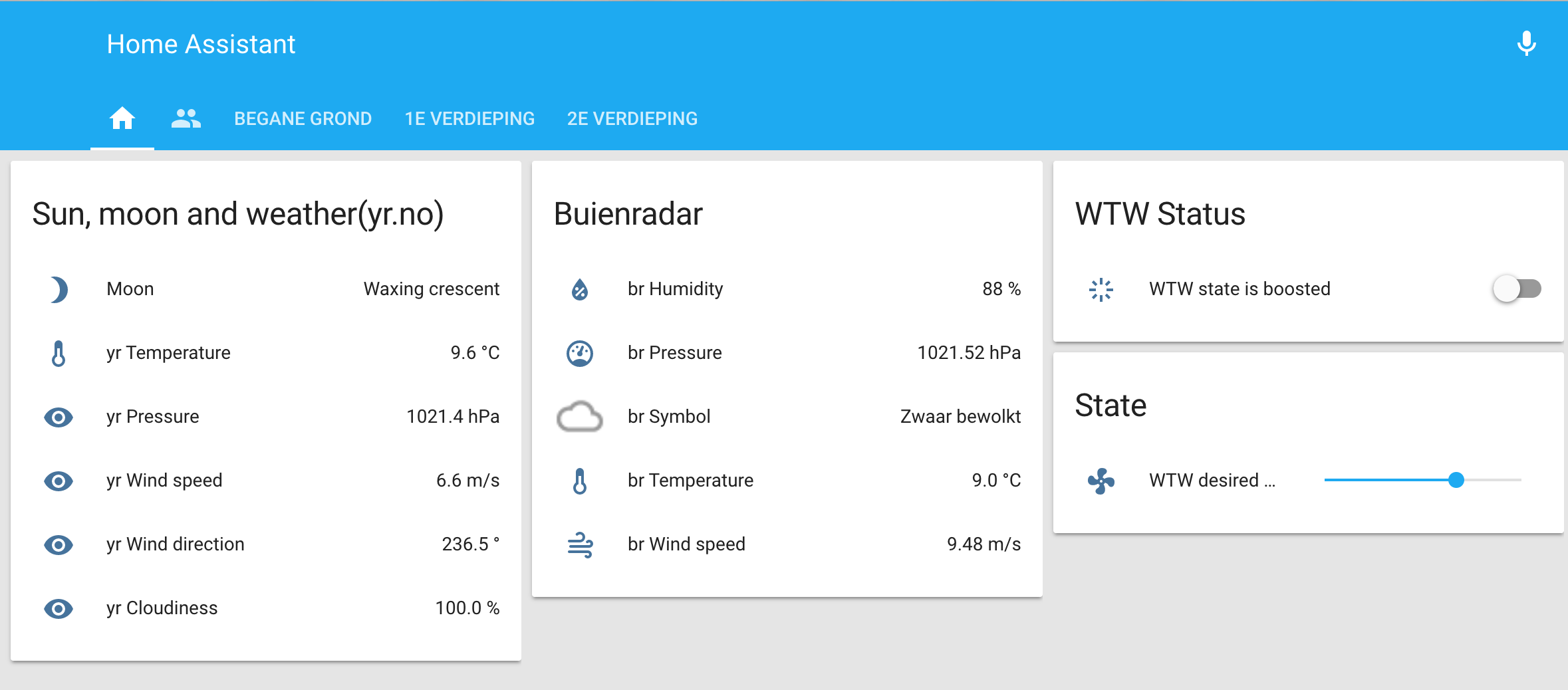
- Define a number (slider) to set the desired WTW state.
The last two are visible on the GUI (see screenshots)
# Include MQTT broker
mqtt:

# Include other files
automation: !include automations.yaml
group: !include groups.yaml
notify: !include notify.yaml
sensor: !include sensor.yaml

# Xiaomi
xiaomi_aqara:
  gateways:
   - mac: <macaddress>
     key: !secret xiaomi_aqara
alert:
  wtw_filter_change:
    name: Your WTW needs a new filter!
    done_message: Your WTW filter is changed. Awesome!
    entity_id: sensor.renoventhr_changefilter
    state: '1'
    repeat: 720 # Every 12 hours
    can_acknowledge: False
    skip_first: False
input_boolean:
  wtw_boost:
    name: WTW state is boosted
    initial: off
    icon: mdi:vanish
input_number:
  wtw_desired_state:
    name: WTW desired state
    min: 0
    max: 3
    initial: 2
    icon: mdi:fan
automations.yaml
In this section we define the automations (or logic) that take place on state changes. I’ve defined a number to make the system as user friendly as possible:
- wtwBoostGUI: Changes the state of the WTW – by publishing a value via MQTT- and switches the mechanical fan to the state defined with the switch on the GUI. It also hides/shows the slider (for desired state) and sends a notification to inform me;
- wtwDesiredState: Change the state of the WTW based on the input provided with the slider;
- wtwFilterChange: Turns on a LED if the filter needs to be changed (and turns it off when its changed);
- bathroom_humidity_high: Sets the wtw Boost switch to True if the humidity is higher than 65%.
- bathroom_humidity_low: Sets the wtw Boost switch to False if the humidity is lower than 60%.
- id: wtwBoostGUI
  alias: 'WTW - Handle actions on boost'
  trigger:
    platform: state
    entity_id: input_boolean.wtw_boost
  action:
    - service: group.set_visibility
      data_template:
        entity_id: group.wtw_user_state
        visible: "{{ trigger.from_state.state }}"
    - service: notify.notify
      data_template:
        title: "WTW boost"
        message: "WTW boost is {{ trigger.to_state.state }}"
    - service_template: >-
            {% if (trigger.to_state.state == 'on') %}
              switch.turn_on
            {% else %}
              switch.turn_off
            {% endif %}
      entity_id:  switch.plug_158d00015dc530
    - service: mqtt.publish
      data_template:
        topic: "RenoventHR/setWTWstate"
        retain: true
        payload: >-
                 {% if (trigger.to_state.state == 'on') %}
                    3
                 {% else %}
                   {{ states.input_number.wtw_desired_state.state | int }}
                 {% endif %}
- id: wtwDesiredState
  alias: wtwDesiredStateSensor
    hide_entity: True
  trigger:
    platform: state
    entity_id: input_number.wtw_desired_state
  action:
    - service: mqtt.publish
      data_template:
        topic: "RenoventHR/setWTWstate"
        retain: true
        payload: '{{trigger.to_state.state | int}}'

- id: wtwFilterChange
  alias: 'WTW - Turn light on if filter needs change'
  trigger:
    platform: state
    entity_id: sensor.renoventhr_changefilter
  action:
    - service: light.turn_off
      entity_id: light.gateway_light_34ce00907b0f
    - condition: state
      entity_id: sensor.renoventhr_filterchange
      state: '1'
    - service: light.turn_on
      entity_id: light.gateway_light_34ce00907b0f
      data:
        color_name: "red"
- id: bathroom_humidity_high
  alias: Monitor humidity in bathoom > 65%
  trigger:
    platform: state
    entity_id: sensor.humidity_158d000170f9aa
  condition:
    condition: and
    conditions:
      - condition: numeric_state
        entity_id: sensor.humidity_158d000170f9aa
        above: 65
      - condition: state
        entity_id: input_boolean.wtw_boost
        state: 'off'
  action:
    - service: notify.notify
      data:
        title: "Bathroom Humidity"
        message: 'Humidity is too high ({{ states.sensor.humidity_158d000170f9aa.state }} %)'
    - service: input_boolean.turn_on
      entity_id: input_boolean.wtw_boost
- id: bathroom_humidity_low
  alias: Monitor humidity in bathoom < 60%
  trigger:
    platform: state
    entity_id: sensor.humidity_158d000170f9aa
  condition:
    condition: and
    conditions:
      - condition: numeric_state
        entity_id: sensor.humidity_158d000170f9aa
        below: 65
      - condition: state
        entity_id: input_boolean.wtw_boost
        state: 'on'
  action:
    - service: notify.notify
      data:
        title: "Bathroom Humidity"
        message: 'The humidity in now okay ({{ states.sensor.humidity_158d000170f9aa.state }} %)'
    - service: input_boolean.turn_off
      entity_id: input_boolean.wtw_boost
customize.yaml
The customize section allows you to customize the look and feel of some sensors. In this case I’m changing the name to a more readable name and icon of the WTW state and Change Filter.
sensor.renoventhr_wtwstate:
  friendly_name: WTW stand
  icon: mdi:fan
sensor.renoventhr_changefilter:
  friendly_name: Filter Vervangen
  icon: mdi:exclamation
groups.yaml
The GUI is mostly configured using the groups section. What components are showed and in what tabs is defined here. In the screenshot you’ll see I’ve put the boost and desired state on the front-page where the actual sensors are in tabs that correspondent to the actual floors.
default_view:
  view: yes
  icon: mdi:home
  entities:
    - group.floor1
    - group.floor2
    - group.wtw_user
    - group.wtw_user_state
    - alert.wtw_filter_change
wtw_user:
  name: WTW Status
  icon: mdi:fan
  entities:
    - input_boolean.wtw_boost
wtw_user_state:
  name: State
  icon: mdi:settings
  entities:
    - input_number.wtw_desired_state
floor1:
  name: 1e verdieping
  view: yes
  entities:
    - group.bathroom
bathroom:
  name: Badkamer
  entities:
    - sensor.humidity_158d000170f9aa
    - sensor.temperature_158d000170f9aa
    - switch.plug_158d00015dc530
floor2:
  name: 2e verdieping
  view: yes
  entities:
    - group.wtw
wtw:
  name: Renovent HR
  entities:
    - sensor.renoventhr_wtwstate
    - sensor.renoventhr_changeFilter
sensor.yaml
Unlike the Xiaomi Agara gateway my module isn’t present by default, it needs to be defined in the sensor section. Since I’ve equipped the module with a MQTT interface I’m using two MQTT sensors and point them to the corresponding topics.
# Renovent HR
  - platform: mqtt
    name: RenoventHR_wtwState
    state_topic: RenoventHR/wtwState
  - platform: mqtt
    name: RenoventHR_changeFilter
    state_topic: RenoventHR/changeFilter
Source Files
If you want to access the PCB design (schematic, board and part list) or the Arduino code, you can find them on Github: https://github.com/
To-do
I know, in the introduction I told you I was finished. Well the module is finished and so is the solution, but I still need to design and print a case for the module. Once that’s finished (and I’m satisfied) I’ll upload another photo.
Hi Ingmar,
I also build a “smart” system for my Brink Renovent ventilation. I just read your post after i build mine. but i notice that my filter signal is not stable. it is constantly changing (it looks likes spikes on the signal line), while the display on the ventilation remains the same. do you experience anything similar?
Hi Ivo,
Yes, I did have the same. Its very easy to resolve by adding a pull-down resistor (R7 in my schema).
Cheers
Hi Ingmar,
Ik ben geinteresseerd in een dergelijke toepassing; maar in feite vind ik het al genoeg als ik de WTW draadloos kan bedienen (stand kan kiezen). Sure, Home Automation is leuk maar voor mij niet nodig in dit geval. Eigenlijk dus de af-fabriek oplossing (van 250+ euro…) maar dan goedkoper. Kan jij daarin iets betekenen? Je mag me e-mailen als je dat wilt.
Bedankt!